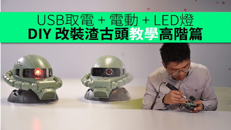
上回改裝達人LED Gundam專頁的版主豬潤 @ 教了渣古頭改裝 LED 燈,今次為大家帶來了高階篇教學:將渣古眼變成可以自己移動。
5mm 紅色LED 燈 x1
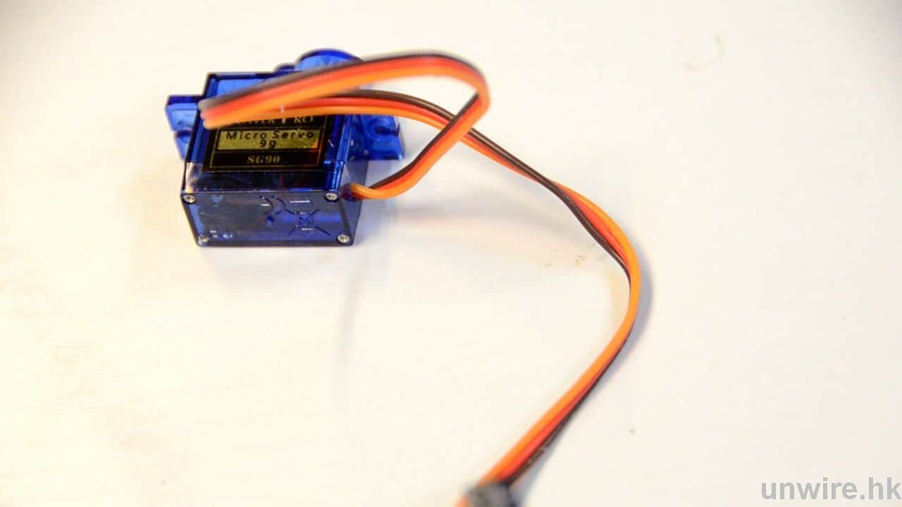
伺服馬達 x1
價錢:HK$20
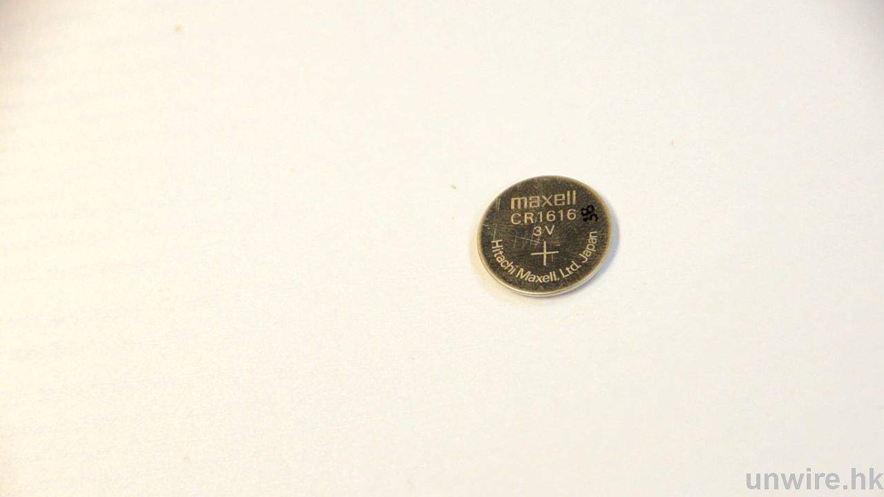
3V鈕形電 x1
價錢:約 HK$5-$10
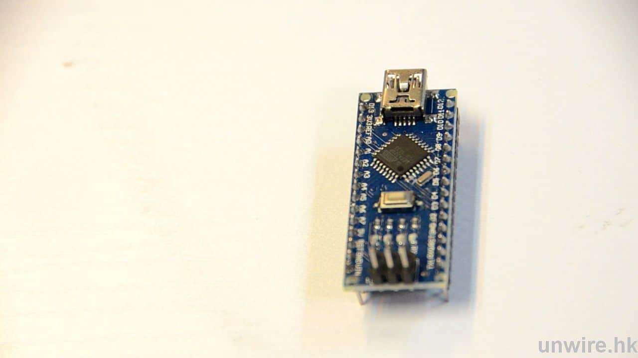
控制伺服摩打的底板Arduino Nano 3.0 x1
價錢:淘寶約 HK$20
銅條 x1
價錢:HK$10
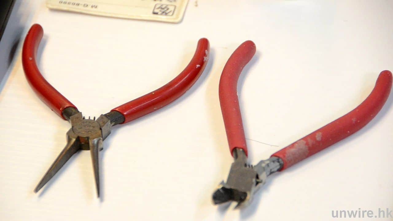
尖嘴鉗 x1 + 切割鉗 x1
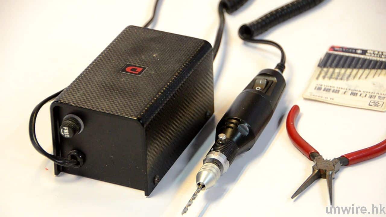
電鑽 x1
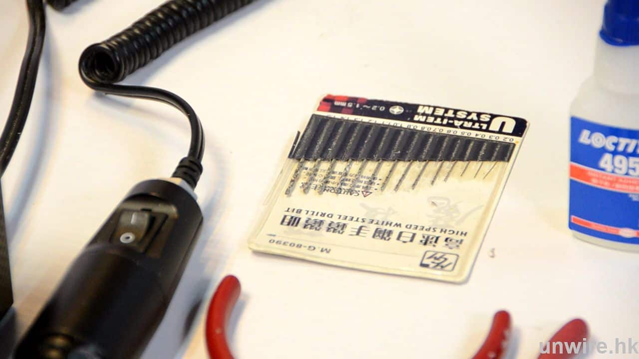
不同大小鑽咀
Step 1: 將渣古頭內支柱剪短
首先要將渣古頭內的一支「樁」(紅圈示) 剪短,因它阻礙之後的安裝伺服馬達的位置。
Step 2: 打磨銀色零件
然後打磨渣古頭內的銀色零件,以電鑽輕力打磨一個適合馬達的體積。
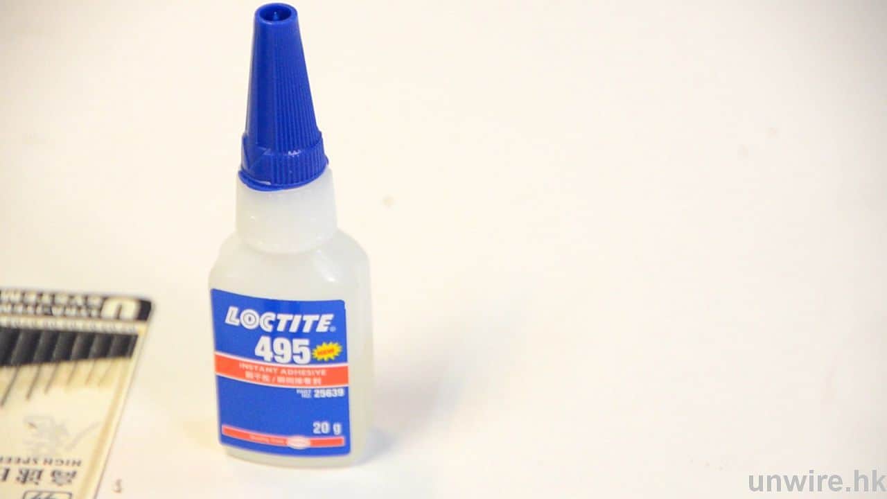
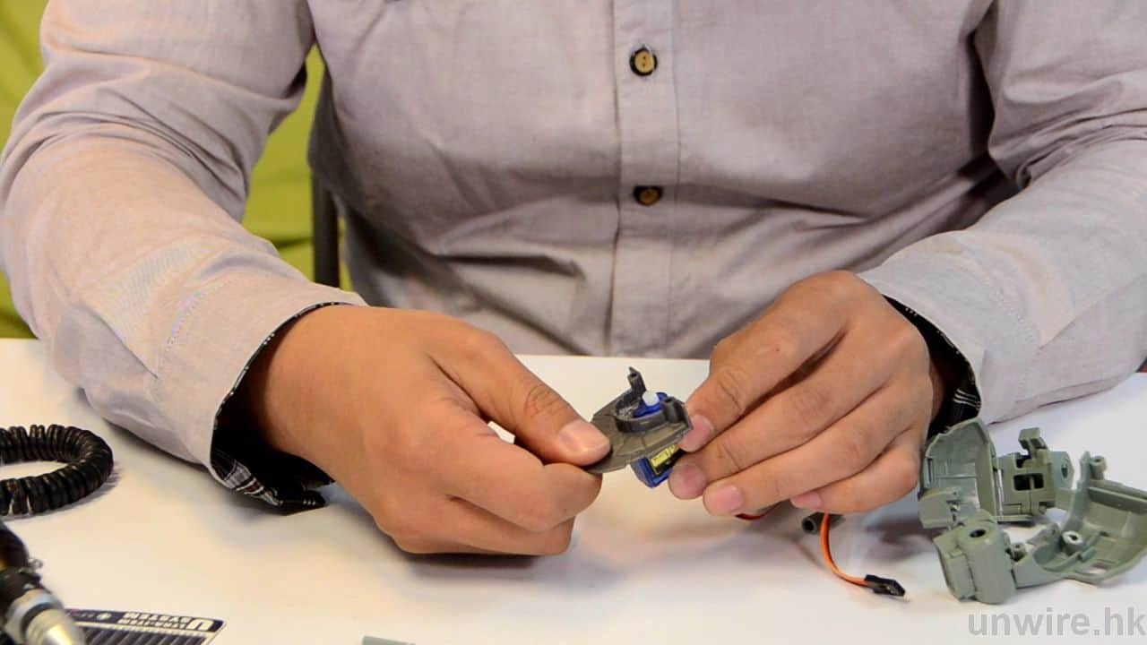
Step3: 膠水固定馬達至銀色零件
適合的話,以膠水固定馬達至銀色零件。
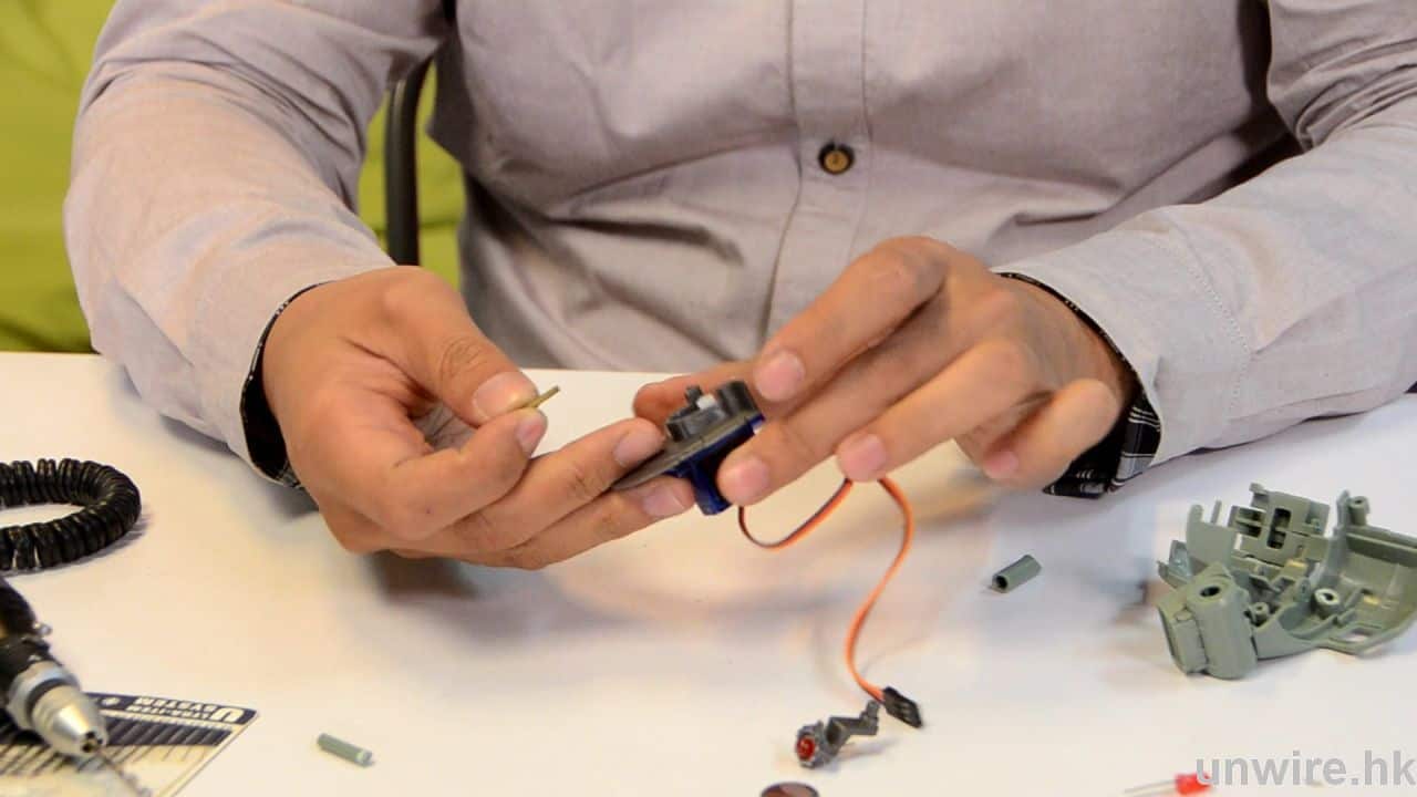
Step 4: 銅條連接眼部與馬達
以銅條連接眼部零件和伺服馬達,如銅條太長可剪短至適合長度。
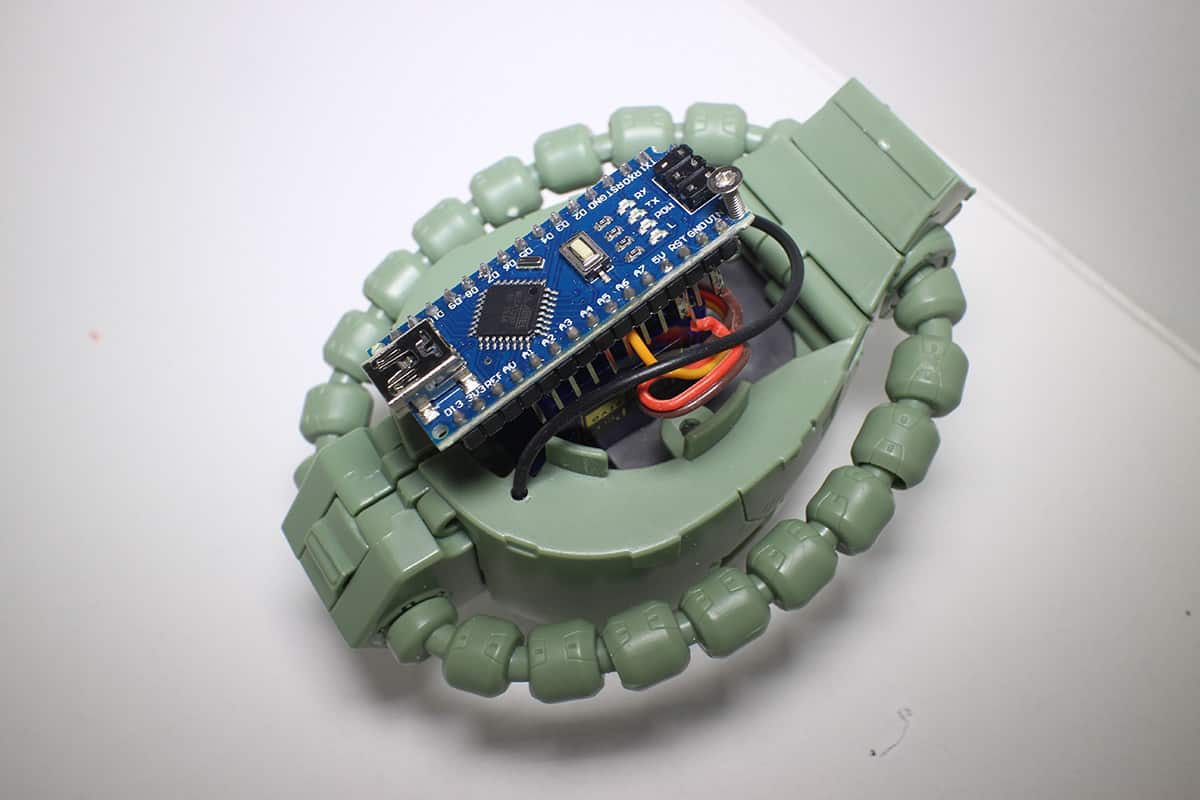
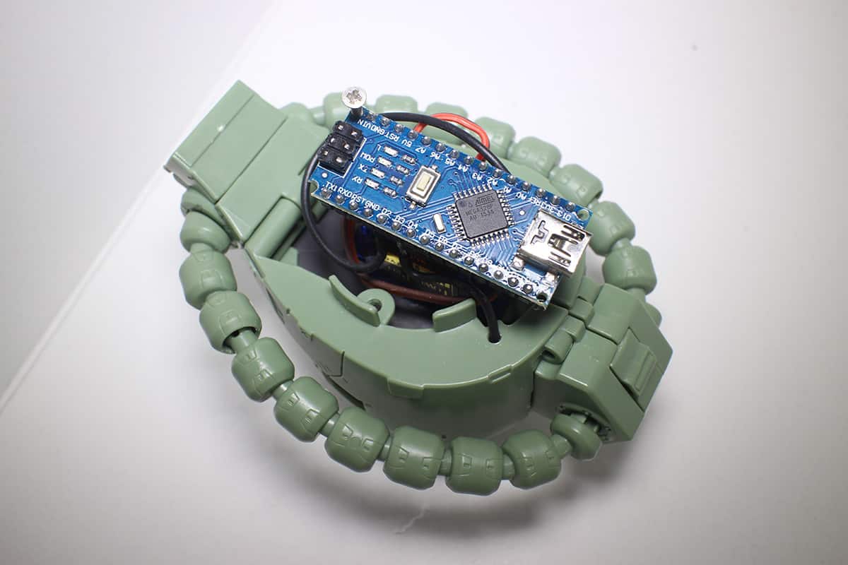
Step 5: 裝上主控底板
最後要裝上主控底板,連接伺服馬達和 LED 的電線,經過頭穿過頸部連接至底板。如圖所示。
Step 6: 電腦傳輸移動設定至底板作控制
控制移動位置和速度的設定要在電腦上 Arduino 軟件預設,只要修改好裡面的參數,並傳輸至底板便可按設定移動。
Step 7: 接上 USB 插頭來供電
之後要移動便要插上 USB 來供電,才可以移動。
教學示範者:LEDGundam版主豬潤
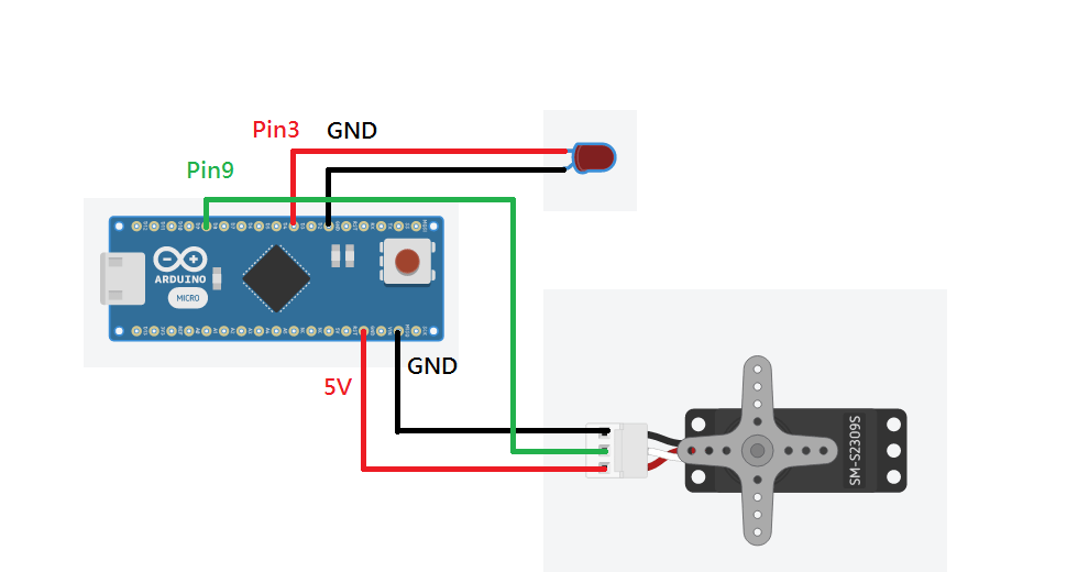
資料更新:有讀者來信查詢,有關電路板的焊接圖及程式碼問題,是次示範的LEDGundam版主豬潤,於是提供了以下的程式碼及焊接圖資料,希望幫到各位讀者。
#include <Servo.h>
Servo myservo; // create servo object to control a servo
// twelve servo objects can be created on most boards
int pos = 100; // variable to store the servo position
int ledpin3 = 3;
void setup() {
myservo.attach(9); // attaches the servo on pin 9 to the servo object
pinMode(ledpin3, OUTPUT);
}
void loop() {
digitalWrite(ledpin3, HIGH);
delay(1000);
for (pos = 99; pos <= 150; pos += 1) { // goes from 0 degrees to 180 degrees
// in steps of 1 degree
myservo.write(pos); // tell servo to go to position in variable ‘pos’
delay(15); // waits 15ms for the servo to reach the position
}
for (pos = 150; pos >= 30; pos -= 1) { // goes from 180 degrees to 0 degrees
myservo.write(pos); // tell servo to go to position in variable ‘pos’
delay(15); // waits 15ms for the servo to reach the position
}
for (pos = 30; pos <= 99; pos += 1) { // goes from 0 degrees to 180 degrees
// in steps of 1 degree
myservo.write(pos); // tell servo to go to position in variable ‘pos’
delay(15); // waits 15ms for the servo to reach the position
}
}